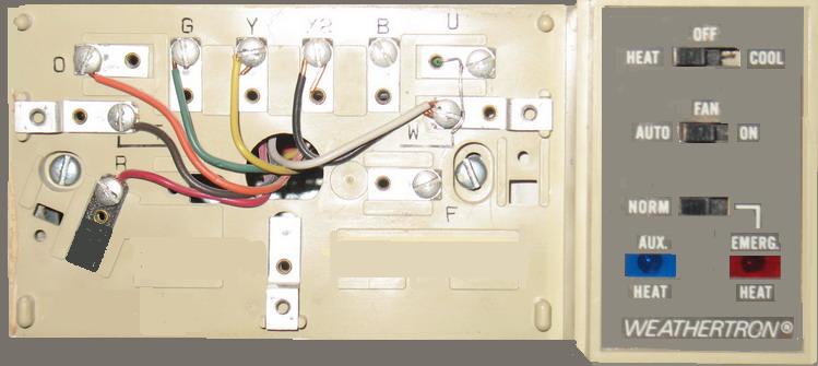
Heating And Cooling Thermostat Wiring Diagram : Wire A Thermostat / C g y o/b rc (jumpered to r) r (jumpered to rc) aux e l.
Heating And Cooling Thermostat Wiring Diagram : Wire A Thermostat / C g y o/b rc (jumpered to r) r (jumpered to rc) aux e l.. Furnace thermostat wiring falls in the diy category that a handy type person can hook up or fix. Typical seven conductor thermostat cable, showing the color of each wire inside. 3 unscrew and remove the base of the thermostat from the wall, and hold onto the wires as you do so. Colors, terminals, functions, voltage path! When changing between heat and cool, the thermostat will turn off the compressor, then wait for mcot.
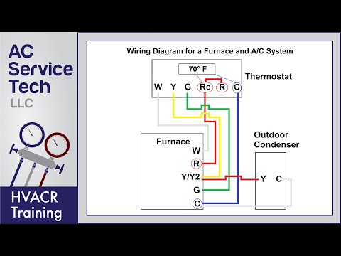
The cooling thermostat is designed to close on a temperature rise and open on a temperature fall. Furnace thermostat wiring falls in the diy category that a handy type person can hook up or fix. The above is a typical wiring diagram of a nest thermostat with 4 wires. 4 wire thermostat wiring color code: Supervision is needed by a licensed hvacr tech while doing this as experience and apprenticeship garners understanding and wiring heat pump thermostats with aux & em.
An air conditioner cooling system is different than a heat pump heating.
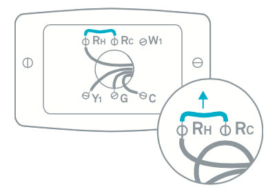
Before doing any work on the thermostat and wiring take a picture off the wires and their connections, or write them. When working with a thermostat the cover can be snapped off to expose the wiring. Nest thermostat connectors wiring diagrams: Operated by heat and magnetism which is proportional to current draw. The instructions diagram for heat pump read The thermostat has 2 modes, heating & cooling, as described in the wiring diagram below. Mounting and wiring your new thermostat 4.1 install new thermostat base. 2 carefully disconnect each wire from the thermostat, and bend them slightly so they do not sink behind the base. Thermostat wiring diagrams wire installation simple guide. Five wire heat/cool systems (refer to page 11) • single stage and two stage heat pump (refer to page 12). W ob remove jumper below w connector. Whether you are designing a simple thermostat or a smart thermostat complete with intuitive hmi and secure wireless connectivity, our reference designs and integrated circuits help you address complex challenges and deliver what's next in thermostat design. If your system can't deliver consistent power to your thermostat to keep its battery charged or correctly control heating and cooling, you may experience one or more of these symptoms
This terminal will call for the need to cool the room when the set temperature is lower than. Heat pump without auxiliary/backup heat. Whether you are designing a simple thermostat or a smart thermostat complete with intuitive hmi and secure wireless connectivity, our reference designs and integrated circuits help you address complex challenges and deliver what's next in thermostat design. 4 wire thermostat wiring color code: Blue wire = y = cooling.
The above is a typical wiring diagram of a nest thermostat with 4 wires.
The instructions diagram for heat pump read Conventional heating and cooling systems. As shown in the diagram, you will need to power up the y terminal is where the signal to the cooling air conditioner signal is connected. Furnace thermostat wiring falls in the diy category that a handy type person can hook up or fix. 4 wire thermostat wiring color code: Nest thermostat connectors wiring diagrams: Allows the fan to run separate from whether heating or cooling is. Disassemble old thermostat and label the wires according to their terminals. Heat pump systems wiring diagrams: The cooling thermostat is designed to close on a temperature rise and open on a temperature fall. Blue wire = y = cooling. Check out multiple thermostat wiring diagrams as well as in depth video explanations on accurately wiring thermostats for various types of hvac systems! Always follow manufacturer wiring diagrams as they will supersede these.
Conventional heating and cooling systems. Heat pump without auxiliary/backup heat. Nest thermostat connectors wiring diagrams: A combination of schematic and pictorial. Unlike other wires connected to your thermostat, a common wire doesn't control heating or cooling functions.
Colors, terminals, functions, voltage path!
Operated by heat and magnetism which is proportional to current draw. Supervision is needed by a licensed hvacr tech while doing this as experience and apprenticeship garners understanding and wiring heat pump thermostats with aux & em. This terminal will call for the need to cool the room when the set temperature is lower than. This video contains 10 wiring diagrams. Conventional heating and cooling systems. Click the icon or the document title to download the pdf. The cooling thermostat is designed to close on a temperature rise and open on a temperature fall. Whether you are designing a simple thermostat or a smart thermostat complete with intuitive hmi and secure wireless connectivity, our reference designs and integrated circuits help you address complex challenges and deliver what's next in thermostat design. Heat pump thermostat wiring explained! C g y o/b rc (jumpered to r) r (jumpered to rc) aux e l. Delay to wait for reversing valve to change over. Nest thermostat connectors wiring diagrams: Separate the thermostat from the the following diagram shows the basic thermostat symbols in the simpl windows' programming manager.


Komentar
Posting Komentar